Flaw Reconstruction Techniques
In nondestructive evaluation of structural material defects, the size, shape, and orientation are important flaw parameters in structural integrity assessment. To illustrate flaw reconstruction, a multiviewing ultrasonic transducer system is shown below. A single probe moved sequentially to achieve different perspectives would work equally as well. The apparatus and the signal-processing algorithms were specifically designed at the Center for Nondestructive Evaluation to make use of the theoretical developments in elastic wave scattering in the long and intermediate wavelength regime.
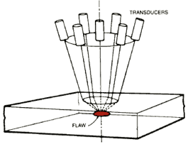 Depicted schematically at the right is the multiprobe system consisting of a sparse array of seven unfocused immersion transducers. This system can be used to "focus" onto a target flaw in a solid by refraction at the surface. The six perimeter transducers are equally spaced on a 5.08 cm diameter ring, surrounding a center transducer. Each of the six perimeter transducers may be independently moved along its axis to allow an equalization of the propagation time for any pitch-catch or pulse-echo combinations. The system currently uses 0.25 in diameter transducers with a nominal center frequency of 10 MHz and a bandwidth extending from approximately 2 to 16 MHz. The axis of the aperture cone of the transducer assembly normally remains vertical and perpendicular to the part surface.
The flaw reconstruction algorithm normally makes use of 13 or 19 backscatter waveforms acquired in a conical pattern within the aperture. The data-acquisition and signal-processing protocol has four basic steps.
- Step one involves the experimental setup, the location and focusing on a target flaw, and acquisition (in a predetermined pattern) of pitch-catch and pulse-echo backscatter waveforms.
- Step two employs a measurement model to correct the backscatter waveforms for effects of attenuation, diffraction, interface losses, and transducer characteristics, thus resulting in absolute scattering amplitudes.
- Step three employs a one-dimensional inverse Born approximation to extract a tangent plane to centroid radius estimate for each of the scattering amplitudes.
- In step four the radius estimates and their corresponding look angles are used in a regression analysis program to determine the six ellipsoidal parameters, three semiaxes, and three Euler angles, defining an ellipsoid which best fits the data.
The inverse Born approximation sizes the flaw by computing the characteristic function of the flaw (defined as unity inside the flaw and zero outside the flaw) as a Fourier transform of the ultrasonic scattering amplitude. The one-dimensional inverse Born algorithm treats scattering data in each interrogation direction independently and has been shown to yield the size of ellipsoidal flaws (both voids and inclusions) in terms of the distance from the center of the flaw to the wavefront that is tangent to the front surface of the flaw. Using the multiprobe ultrasonic system, the 1-D inverse Born technique is used to reconstruct voids and inclusions that can be reasonably approximated by an equivalent ellipsoid. So far, the investigation has been confined to convex flaws with a center of inversion symmetry. The angular scan method described in this paper is capable of locating the bisecting symmetry planes of a flaw. The utility of the multiprobe system is, therefore, expanded since two-dimensional elliptic reconstruction may now be made for the central slice. Additionally, the multiprobe system is well suited for the 3-D flaw reconstruction technique using 2-D slices.
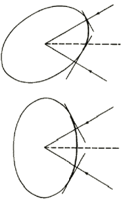 The model-based reconstruction method has been previously applied to voids and incursion flaws in solids. Since the least-squares regression analysis leading to the "best fit" ellipsoid is based on the tangent plane to centroid distances for the interrogation directions confined within a finite aperture. The success of reconstruction depends on the extent of the flaw surface "illuminated" by the various viewing directions. The extent of coverage of the flaw surface by the tangent plane is a function of the aperture size, flaw shape, and the flaw orientation. For example, a prolate spheroidal flaw with a large aspect ratio oriented along the axis of the aperture cone will only have one tip illuminated (i.e., covered by the tangent planes) and afford a low reconstruction reliability. For the same reason, orientation of the flaw also has a strong effect on the reconstruction accuracy.
The diagram on the right shows the difference in surface coverage of a tilted flaw and an untilted flaw subjected to the same insonification aperture. Both the experimental and simulation studies of the aperture effect reported before were conducted for oblate and prolate spheroids oriented essentially symmetrically with respect to the part surface and hence the aperture cone. From a flaw reconstruction standpoint, an oblate spheroid with its axis of rotational symmetry perpendicular to the part surface represents a high leverage situation. Likewise, a prolate spheroid with its symmetry axis parallel to the part surface also affords an easier reconstruction than a tilted prolate spheroid. In this CNDE project, we studied effects of flaw orientation on the reconstruction and derived a new data-acquisition approach that will improve reliability of the new reconstruction of arbitrarily oriented flaws.
The orientation of a flaw affects reconstruction results in the following ways.
- For a given finite aperture, a change in flaw orientation will change the insonified surface area and hence change the "leverage" for reconstruction.
- The scattering signal amplitude and the signal/noise ratio for any given interrogation direction depends on the flaw orientation.
- Interference effects, such as those due to tip diffraction phenomena or flash points may be present at certain orientations. Of course, interdependencies exist in these effects, but for the sake of convenience they are discussed separately in the following.
Aperture
To assess the effects of finite aperture size on flaws of different orientation, computer simulations were performed for an oblate spheroid with semi-axes of 400, 400, and 200 µm that is tilted and untilted with respect to the part surface. For each of the 13 scattering directions, the exact radius estimates Re (i.e. the tangent plane to centroid distances) were first computed, and a random error in sizing was then introduced to simulate the experimental situation. The radius estimate used was then taken to be
where n is a randomly generated number between ±0.1. Using the Re' values for the various directions, a best fit ellipsoid is determined using a regression program. This process is repeated 100 times for each aperture angle and mean standard deviation of the three semiaxes is expressed as a percentage of the expected values. The simulation was performed for the untilted case with the 400 x 400 µm plane parallel to the part surface and for a tilt angle of 40ƒ from the normal of the part surface. The results are summarized in Table I.
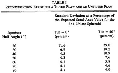
The mean values for the ellipsoidal semi-axes converge to expected values, while the standard deviations converge to some asymptotic minimum. The values in Table I show that for a small aperture, the standard deviation as a percentage of expected value (an indication of the reconstruction error) is much higher for the oblate spheroid tilted at 40ƒ with respect to the horizontal than is the 0ƒ untilted case. As the aperture increases, the difference in reconstruction error approaches zero because surface illumination is sufficient to ensure a reliable reconstruction. Due to the combined effect of finite aperture and a prior unknown flaw orientation, a large aperture is desirable to increase reliability of reconstruction results.
Note that in this simulation only the aperture angle is increased, and the number of interrogation directions remains unchanged. The number of look directions is kept the same because the multiviewing system is intended for acquiring a sparse array of data based on speed considerations.
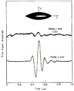
For a given scattering direction amplitude of the scattering amplitude and, therefore, the signal/noise ratio depend on orientation of the flaw. In the short wavelength limit scattering amplitude is proportional to square root of (R1 R2) with R1 and R2 being the principal radii of curvature of the flaw for the scattering direction used. This dependence is found to be important in the intermediate frequency regime as well. To illustrate this effect, the figure at the right shows the scattered signal amplitudes from a football-shaped prolate spheroidal void with two cusp-like tips in two directions: broadside and along the tips. The profile of the tips can increase the ratio of the two signal amplitudes as large as 35.
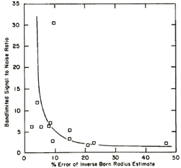
To investigate the correlation between the accuracy of flaw sizing and signal/noise ratio of the flaw waveform at different scattering directions, a 400 x 400 x 200 µm oblate spheroidal void in titanium with its axis of rotational symmetry tilted at a 30ƒ angle from normal to the part surface was reconstructed using the multiviewing transducer system. It was found that sizing results were generally more accurate for the scattering directions with a higher signal/noise ratio, as expected. Furthermore, the directions that gave the poorest signal/noise ratios were often ones closest to being in an edge-on perspective. The figure on the right shows the relationship between the percentage error of the radius estimate and signal/noise ratio of the flaw waveform. Reconstruction results of the oblate spheroid void tilted at 30ƒ are listed in Table II.
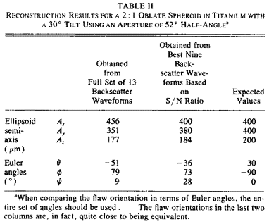
The reconstruction results of both the semi-axes length and tilt angle were improved by rejecting four data points with the lowest signal/noise ratios. Since multiviewing transducer system provides a maximum of 19 independent look angles for a given tilt angle of the transducers, rejecting a small subset of the data points based on signal/noise consideration still leaves a sufficient number of data points for the ellipsoidal regression step which requires a minimum of six data points.
Flash Point Interference
The multiview transducer system and associated signal-processing algorithms reconstruct a flaw based on a general ellipsoid model. For ellipsoids with a large aspect ratio and flaw shapes that approach those of a flat crack or a long needle, edge or tip diffractions due to points of stationary phase (flash points) governed by, geometric acoustics become important. When such phenomena are present within the transducer bandwidth, the scattered signal frequency spectrum contains strong interference maxima and minima and renders radius estimates by the 1-D inverse Born difficult or impossible.
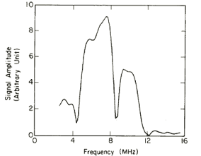
The figures below show a test flaw in the form of a copper wire segment embedded in a transparent thermoplastic disk and tilted at 45ƒ with respect to the disk surface and the frequency spectrum of the wire inclusion at a scattering angle of 21ƒ from the wire axis. The strong interference pattern prevented the I-D inverse Born algorithm from yielding a meaningful radius estimate. However, when the spectrum was analyzed on assumption of flash point interference (without having to use the angle information), 321 µm was obtained for a path length difference of the stationary phase points in the scattering direction; this compared reasonably well with 374 µm for twice the tangent plane distance in this orientation.
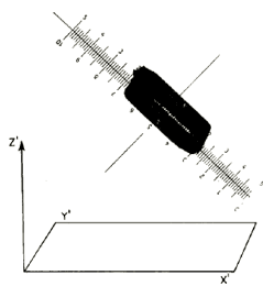
In the photomicrograph of copper wire segment titled at 45ƒ and embedded in thermoplastic. Each minor division of scale is 10 µm, and wire segment is approximately prolate spheroid with semi-axes Ax = 80 µm, Ay = 80 µm, and Az = 200 µm.
Spatial Data-acquisition Pattern For Arbitrarily Oriented Flaw
From the investigation described earlier, it is clear that reliable reconstruction of an arbitrarily oriented flaw generally requires a large aperture. However, a large viewing aperture perpendicular to the part surface may still contain scattering directions hampered by weak flaw signal amplitude (poor signal-to-noise ratio) and, in certain cases, flash point interference. A predetermined data-acquisition pattern that is relatively free from such disadvantages can improve reconstruction reliability. In this work we explored a method to predetermine a spatial pattern for data acquisition. This pattern affords a high leverage for reliable reconstruction for arbitrarily oriented flaws that can be approximated by the shape of a spheroid.
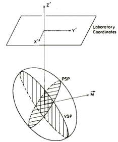 Consider a tilted prolate spheroid as shown on the right. We may define a vertical sagittal plane (VSP) as the plane that bisects the flaw and contains the z axis. We further define a perpendicular sagittal plane (PSP) as the plane bisecting the spheroid and perpendicular to the VSP. The intersection of the VSP and PSP (direction M in diagram) then corresponds to a direction of maximum flaw signal amplitude. The orientation of the VSP can be located by a series of azimuthal scans at different polar angles. A maximum in the signal amplitude should be observed at the azimuthal angle of the VSP. This definition of the VSP and PSP and their relationship to backscattered flaw signal amplitude also holds true for an oblate spheroid. Below shows the azimuthal scans at four different polar angles for the 2.5:1 prolate spheroid (wire segment) flaw. Once the azimuthal angle of the VSP is determined (30ƒ in this case), a polar scan below at the azimuthal angle of the VSP determines the tilt angle of the wire segment to be 41ƒ, as compared to 45ƒ from optical measurement.
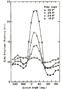
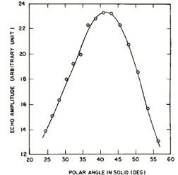
Flaw signal amplitude as a function of azimuthal and polar angles.
The angular scans serve two very useful functions. First, they provide some information about the shape and orientation of the flaw. For example, a scan in the perpendicular sagittal plane can distinguish a prolate spheroid from an oblate spheroid by changing the polar angle and the azimuthal angle simultaneously. A scan in the PSP of the 2:1 oblate spheroid tilted at 30ƒ showed a peak in flaw signal amplitude at the intersection of the VSP and the PSP (direction M), whereas a scan in the PSP of the tilted 2.5:1 prolate spheroid showed a constant flaw signal amplitude.
Second, it provides a basis for predetermining a spatial data-acquisition pattern that is equivalent to a tilted aperture cone centered at direction M. This data-acquisition pattern not only ensures good signal-to-noise ratio, avoids possible flash point interference due to end-on or edge-on perspectives, and provides a maximum illuminated area on the flaw surface, but also allows one to reconstruct the flaw with two mutually orthogonal elliptical cross sections in the VSP and PSP.
So far, the discussion of angular scans has been confined to flaws that are approximately spheroidal in shape. For a general ellipsoid with three unequal semi-axes and oriented arbitrarily in space, the angular scan results will be more complicated. For example, an azimuthal scan at different polar angles is not expected to show a peak at the same azimuthal angle. Shape and orientation information, in principle, can still be extracted from such data, and further investigations are underway for the general case.
Reconstruction Results
To verify the reconstruction method using the new spatial data-acquisition configuration experimentally, reconstructions were performed on two test specimens. The first flaw was the 400 µm long 80 µm radius copper wire segment embedded in a thermoplastic disk. This flaw was used to approximate a prolate spheroid with a 2.5:1 aspect ratio. The axis of the wire segment was at a 45ƒ angle relative to the part surface. The second flaw was a 400 x 200 µm oblate spheroidal void tilted at a 30ƒ angle in a diffusion bonded titanium disk, as just described.
The flaw reconstruction procedure using an aperture cone perpendicular to the part surface was first carried out for the 2.5:1 prolate inclusion (copper wire) tilted at a 45ƒ angle. Difficulties due to a poor signal-to-noise ratio and flash point interference associated with look directions close to the end-on perspective prevented a successful reconstruction; in fact, enough inconsistencies occurred in the tangent plane distance estimates that the regression step failed to converge.
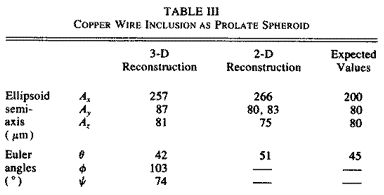
Based on orientations of the sagittal planes determined in the angular scans, the new data-acquisition pattern equivalent to tilting the aperture axis to the direction of maximum signal strength was used. The ellipsoidal reconstruction gave a tilt angle of 42ƒ and three semiaxes of 257, 87, and 81 µm. These results compared very favorably with the actual tilt angle of 45ƒ and the actual semi-axes of 200, 80, and 80 µm.
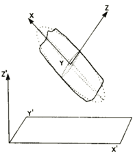 The new data-acquisition pattern also allows one to reconstruct an arbitrarily tilted spheroidal flaw with the two mutually orthogonal elliptical cross-sectional cuts in the VSP and PSP. This was done for the copper wire inclusion. After identifying the vertical sagittal plane and the perpendicular sagittal plane, a series of tangent plane distance estimates were made for scattering directions confined in these two planes. Using these results, the two mutually orthogonal elliptical cross sections in the VSP and PSP were reconstructed using a similar regression program in 2-D. The two reconstructed ellipses were 266 x 83 µm and 80 x 75 µm, respectively, and the tilt angle was found to be 51ƒ. Table III shows the results of the 3-D reconstruction using 19 look perspectives and the 2-D reconstruction of the ellipses in the VSP and PSP. Both reconstructions compared very favorably with the expected values. The greatest discrepancy is in the value of the semi-axis Ax; this is to be expected because the wire segment is approximately a prolate spheroid with two ends truncated.
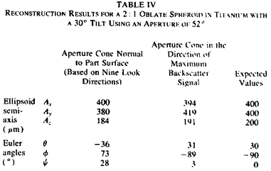
The 2:1 oblate spheroidal void tilted at a 30ƒ angle in a titanium disk was investigated, again, following the procedure of predetermining a favorable data-acquisition pattern based on angular scan results. Table IV shows the reconstruction results using the new data-acquisition pattern equivalent to an aperture cone centered on the direction of maximum backscatter signal. As a comparison, reconstruction results using an aperture cone normal to the part surface (described earlier) are also shown. As can be seen, the improvement of the reconstruction by using the new data-acquisition pattern is not as dramatic as the prolate inclusion case. This is consistent with the fact that the oblate spheroid has a smaller aspect ratio and a smaller tilt angle and is therefore not nearly a "low leverage" flaw to reconstruct using the normal (untilted) data-acquisition pattern.
The reliability problem of reconstructing arbitrarily oriented flaws using the multiviewing transducer system and associated model-based algorithm has been studied. An arbitrarily oriented flaw may afford a low leverage for reconstructing the entire flaw based on limited surface area covered by the tangent planes in a finite aperture and, therefore, requires a greater aperture for a reliable reconstruction. However, the aperture size has practical limits in a single-side access inspection situation and a larger aperture does not necessarily alleviate such difficulties as poor signal-to-noise ratio and flash point interference associated with certain interrogation directions. In our study of reconstructing approximately spheroidal flaws oriented at some arbitrary angle, it was found beneficial to predetermine a spatial data-acquisition pattern based on angular dependence of the flaw signal amplitude. The new data-acquisition pattern is equivalent to tilting the interrogation aperture cone to compensate for the particular orientation of the flaw and restore the leverage for a more reliable reconstruction. This method worked well on two test cases.