Crack Tip Diffraction
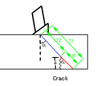
When the geometry of the part is relatively uncomplicated and the orientation of a flaw is well known, the length (a) of a crack can be determined by a technique known as tip diffraction. One common application of the tip diffraction technique is to determine the length of a crack originating from on the backside of a flat plate as shown below. In this case, when an angle beam transducer is scanned over the area of the flaw, the principle echo comes from the base of the crack to locate the position of the flaw (Image 1). A second, much weaker echo comes from the tip of the crack and since the distance traveled by the ultrasound is less, the second signal appears earlier in time on the scope (Image 2).


Crack height (a) is a function of the ultrasound velocity (v) in the material, the incident angle (Q2) and the difference in arrival times between the two signal (dt). Since the incident angle and the thickness of the material is the same in both measurements, two similar right triangle are formed such that one can be overlayed on the other. A third similar right triangle is made, which is comprised on the crack, the length dt and the angle Q2. The variable dt is really the difference in time but can easily be converted to a distance by dividing the time in half (to get the one-way travel time) and multiplying this value by the velocity of the sound in the material. Using trigonometry an equation for estimating crack height from these variables can be derived as shown below.

Solving for "a" the equation becomes
The equation is complete once distance dt is calculated by dividing the difference in time between the two signals (dt) by two and multiplying this value by the sound velocity.