Automated Scanning
 Ultrasonic scanning systems are used for automated data acquisition and imaging. They typically integrate a ultrasonic instrumentation, a scanning bridge, and computer controls. The signal strength and/or the time-of-flight of the signal is measured for every point in the scan plan. The value of the data is plotted using colors or shades of gray to produce detailed images of the surface or internal features of a component. Systems are usually capable of displaying the data in A-, B- and C-scan modes simultaneously. With any ultrasonic scanning system there are two factors to consider:
- how to generate and receive the ultrasound.
- how to scan the transducer(s) with respect to the part being inspected.
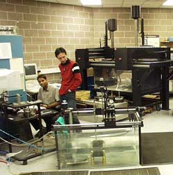
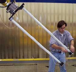
 The most common ultrasonic scanning systems involve the use of an immersion tank as shown in the image above. The ultrasonic transducer and the part are placed under water so that consistent coupling is maintained by the water path as the transducer or part is moved within the tank. However, scanning systems come in a large variety of configurations to meet specific inspection needs. In the image to the right, an engineer aligns the heads of a squirter system that uses a through-transmission technique to inspect aircraft composite structures. In this system, the ultrasound travels through columns of forced water which are scanned about the part with a robotic system. A variation of the squirter system is the "Dripless Bubbler" scanning system, which is discussed below.
It is often desirable to eliminate the need for the water coupling and a number of state-of-the-art UT scanning systems have done this. Laser ultrasonic systems use laser beams to generate the ultrasound and collect the resulting signals in an noncontact mode. Advances in transducer technology has lead to the development of an inspection technique known as air-coupled ultrasonic inspection. These systems are capable of sending ultrasonic energy through air and getting enough energy into the part to have a useable signal. These system typically use a through-transmission technique since reflected energy from discontinuities are too weak to detect.
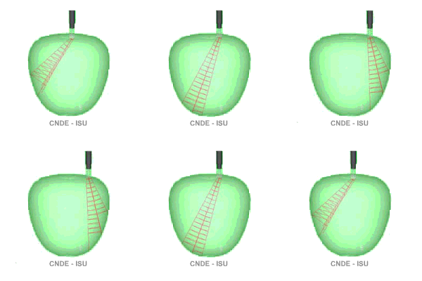
 The second major consideration is how to scan the transducer(s) with respect to the part being inspected. When the sample being inspected has a flat surface, a simple raster-scan can be performed. If the sample is cylindrical, a turntable can be used to turn the sample while the transducer is held stationary or scanned in the axial direction of the cylinder. When the sample is irregular shaped, scanning becomes more difficult. As illustrated in the beam modeling animation, curved surface can steer, focus and defocus the ultrasonic beam. For inspection applications involving parts having complex curvatures, scanning systems capable of performing contour following are usually necessary.