Transducer Testing
Some transducer manufacturers have lead in the development of transducer characterization techniques and have participated in developing the AIUM Standard Methods for Testing Single-Element Pulse-Echo Ultrasonic Transducers as well as ASTM-E 1065 Standard Guide for Evaluating Characteristics of Ultrasonic Search Units.
Additionally, some manufacturers perform characterizations according to AWS, ESI, and many other industrial and military standards. Often, equipment in test labs is maintained in compliance with MIL-C-45662A Calibration System Requirements. As part of the documentation process, an extensive database containing records of the waveform and spectrum of each transducer is maintained and can be accessed for comparative or statistical studies of transducer characteristics.
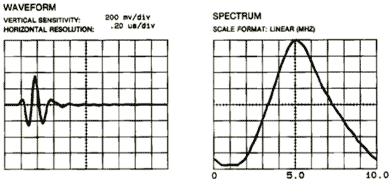
Manufacturers often provide time and frequency domain plots for each transducer. The signals below were generated by a spiked pulser. The waveform image on the left shows the test response signal in the time domain (amplitude versus time). The spectrum image on the right shows the same signal in the frequency domain (amplitude versus frequency). The signal path is usually a reflection from the back wall (fused silica) with the reflection in the far field of the transducer.

Other tests may include the following:
- Electrical Impedance Plots provide important information about the design and construction of a transducer and can allow users to obtain electrically similar transducers from multiple sources.
- Beam Alignment Measurements provide data on the degree of alignment between the sound beam axis and the transducer housing. This information is particularly useful in applications that require a high degree of certainty regarding beam positioning with respect to a mechanical reference surface.
- Beam Profiles provide valuable information about transducer sound field characteristics. Transverse beam profiles are created by scanning the transducer across a target (usually either a steel ball or rod) at a given distance from the transducer face and are used to determine focal spot size and beam symmetry. Axial beam profiles are created by recording the pulse-echo amplitude of the sound field as a function of distance from the transducer face and provide data on depth of field and focal length.