Pulser-Receivers
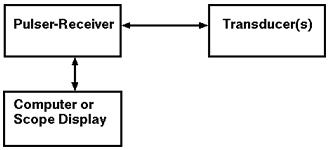
Ultrasonic pulser-receivers are well suited to general purpose ultrasonic testing. Along with appropriate transducers and an oscilloscope, they can be used for flaw detection and thickness gauging in a wide variety of metals, plastics, ceramics, and composites. Ultrasonic pulser-receivers provide a unique, low-cost ultrasonic measurement capability.

The pulser section of the instrument generates short, large amplitude electric pulses of controlled energy, which are converted into short ultrasonic pulses when applied to an ultrasonic transducer. Most pulser sections have very low impedance outputs to better drive transducers. Control functions associated with the pulser circuit include:
- Pulse length or damping (The amount of time the pulse is applied to the transducer.)
- Pulse energy (The voltage applied to the transducer. Typical pulser circuits will apply from 100 volts to 800 volts to a transducer.)
In the receiver section the voltage signals produced by the transducer, which represent the received ultrasonic pulses, are amplified. The amplified radio frequency (RF) signal is available as an output for display or capture for signal processing. Control functions associated with the receiver circuit include
- Signal rectification (The RF signal can be viewed as positive half wave, negative half wave or full wave.)
- Filtering to shape and smooth return signals
- Gain, or signal amplification
- Reject control
 The pulser-receiver is also used in material characterization work involving sound velocity or attenuation measurements, which can be correlated to material properties such as elastic modulus. In conjunction with a stepless gate and a spectrum analyzer, pulser-receivers are also used to study frequency dependent material properties or to characterize the performance of ultrasonic transducers.