Materials Characterization Methodologies
As discussed above, materials characterization is an important aspect of microwave NDE. Performing materials characterization (i.e., determining the permittivity and/or permeability which intrinsically describe a material at microwave frequencies) allows for determination of chemical and physical makeup of a material. It can also provide information about the mechanical properties of a material, can tell us how a material is changing over time, can provide necessary information for performing electromagnetic modeling, and more!
The techniques used for performing materials characterization can be generally grouped into a few different categories of techniques: resonant, reflection, and transmission.
In resonant techniques, devices such as a resonant cavity (pictured in previous section), microstrip resonator, or dielectric resonator are often used. The general principle of resonant techniques is to relate the resonance frequency and Quality factor (Q factor) of the resonance to the material property of interest. These methods tend to be good for low loss materials. However, they often require that the sample be prepared in a precise shape, meaning that these methods are generally “destructive” unless liquids or granular materials are being measured.
In reflection techniques, open-ended waveguide probes and open-ended coaxial probes are typically and primarily used to make measurements. While both coaxial probes and waveguide probes are inherently broadband, waveguide probes are typically used at higher frequencies because as coaxial probes become relatively smaller with increasing frequency are generally poorer radiators.
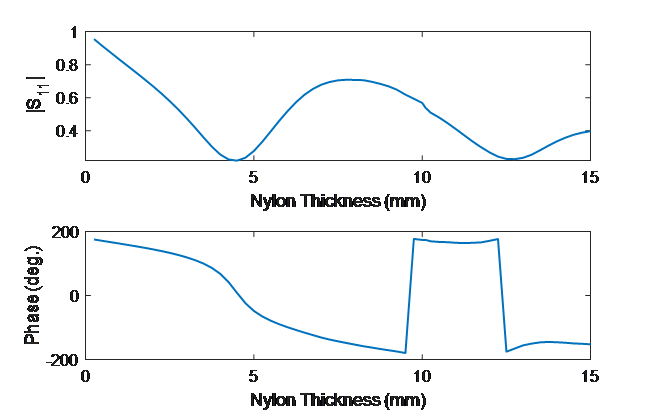
To make the measurement the probe is placed on the surface of or above the material of interest and S11 is measured. The material under test can be a single layer structure or a multi-layer structure. As an example, the reflection coefficient, S11, conductor-backed nylon (complex dielectric constant of 3.04-j0.03) with varying nylon thickness was simulated. The gif and plot below show how (complex) S11 changes as a function of nylon thickness. If the thickness or dielectric constant of the nylon were unknown, a forward-iterative model could be used to determine them based on the S11 response.

Change in S11 in the polar plot as a function of nylon thickness.

Average magnitude and phase of S11 over frequency for different conductor backed nylon thicknesses.
The conductor backing in the example above strongly reflects the microwave signal produced by the waveguide and this increases the sensitivity to thickness. When a material is thick and lossy enough it appears infinitely thick and consequently there is not a strong reflection from the backside of the material that influences the response. This is illustrated in the gif below which shows the electric field inside of a conductor backed nylon structure and in an infinitely thick layer of nylon.
