What is Being Measured?
There are numerous approaches when it comes to making microwave measurements. Ultimately, the chosen or relevant measurement approach ends up being application-dependent. Consequently, the type of measurement and the instrument used to measure the parameter of interest varies substantially.
In some applications a threshold may be set to determine whether a critical event has taken place. An example of this would be if the thickness of a coating layer has been reduced to a certain critical level as a result of in-service wear and tear, or if the coating thickness is of interest in a manufacturing process (e.g., paint, thermal barrier coating (TBC), etc.). In this case a relatively simple reflectometer may be devised, which provides a DC output voltage as a function of thickness. This renders a simple and easy measurement approach. In other applications in which complex permittivity (or permeability) is sought, leading to for example materials property characterization, complex reflection and/or transmission coefficient, as function of frequency may be sought. To this end, the measurement approach will require a calibrated vector network analyzer (VNA). In such measurements, a commensurate electromagnetic model describing or predicting the measured reflection or transmission coefficient is usually needed, as well. Then, subsequent to making a proper measurement, the model can be used either in a direct inversion or a forward-iterative manner, to extract the parameters of interest (i.e., complex permittivity). Finally, using an appropriate dielectric mixing formula, the measured complex permittivity is related to material properties, such as: volumetric porosity, cure state, chemical make-up, multiple thickness in a layered structure, disbond/delamination location and thickness, etc.
Independent of the particular measurement approach used, there needs to be an irradiating microwave signal that irradiates the sample-under-test (SUT) at a certain frequency or in a frequency range, polarization and with some particular wave properties (i.e., plane-wave, TE & TM waveguide modes, etc.). The reflected from and/or transmitted through signals will have to be detected, which is usually accomplished by measuring the reflection or transmission coefficient (i.e., complex ratio of the reflected or transmitted signal to the irradiating signal). A multi-port and wideband VNA facilitates this type of measurement. In addition, the VNA once calibrated, gives actual values of magnitude and phase of reflection and transmission coefficients, as a function of frequency. These reflection and transmission coefficients are referred to as the scattering parameters or the S-parameters for short. For a two-port VNA, the following S-parameters can be measured:
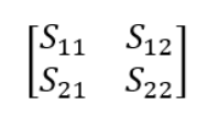
In the matrix above, the first subscript represents the port at which the measurement is conducted and the second subscript represents the port from which the signal originated (i.e., S11 is the signal at port 1 from port 1). S11 is also referred to as the reflection coefficient because it represents the ratio of the signal that is reflected back to port 1 to the signal that is transmitted from port 1. Similarly, S12 is also referred to as the transmission coefficient because it represents the signal that is transmitted to port 1 from port 2. Many microwave devices are reciprocal, meaning that S12=S21. The matrix and convention described above can be extended for VNAs with more ports (e.g., a 4-port VNA).
Which S-parameter we examine and how we examine it again depends on the application. On a typical VNA, like the one shown in the previous section, we can view a single or multiple S-parameters at the same time and in different formats, such as a log magnitude plot, a phase plot, a polar plot, a Smith chart, etc. The example below shows a two-port waveguide measurement setup that is typical in materials characterization: two waveguide to coax adapters are connected together with a short section of waveguide sandwiched in between them. The short section of waveguide contains a precisely cut block of a material. The VNA screenshots show all four S-parameters in a couple different formats. The S-parameters can be saved to files that can then be analyzed or put into an electromagnetic model on a computer.
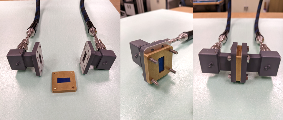
Measurement setup for 2-port filled waveguide measurements for characterizing a dielectric material.
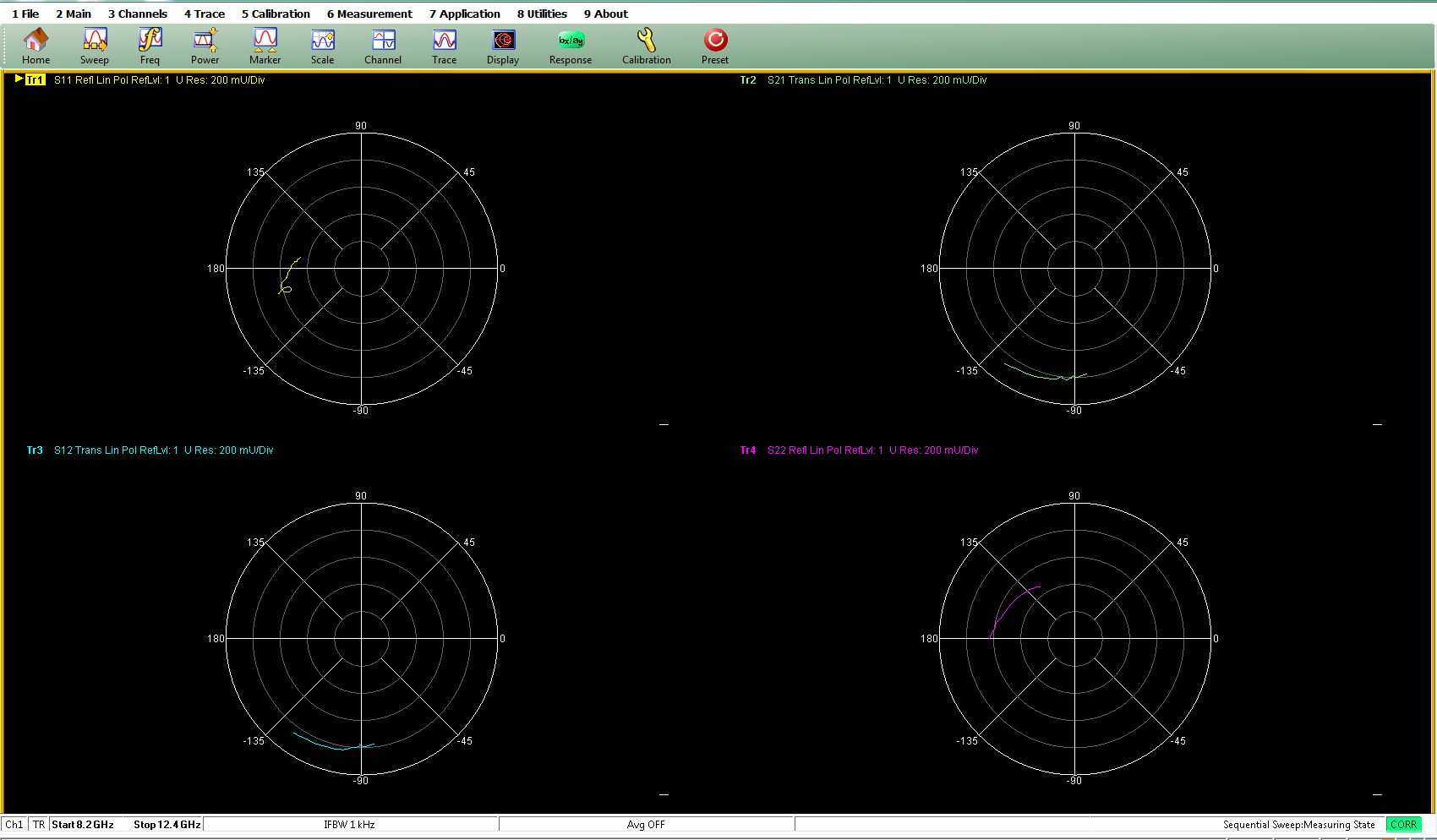
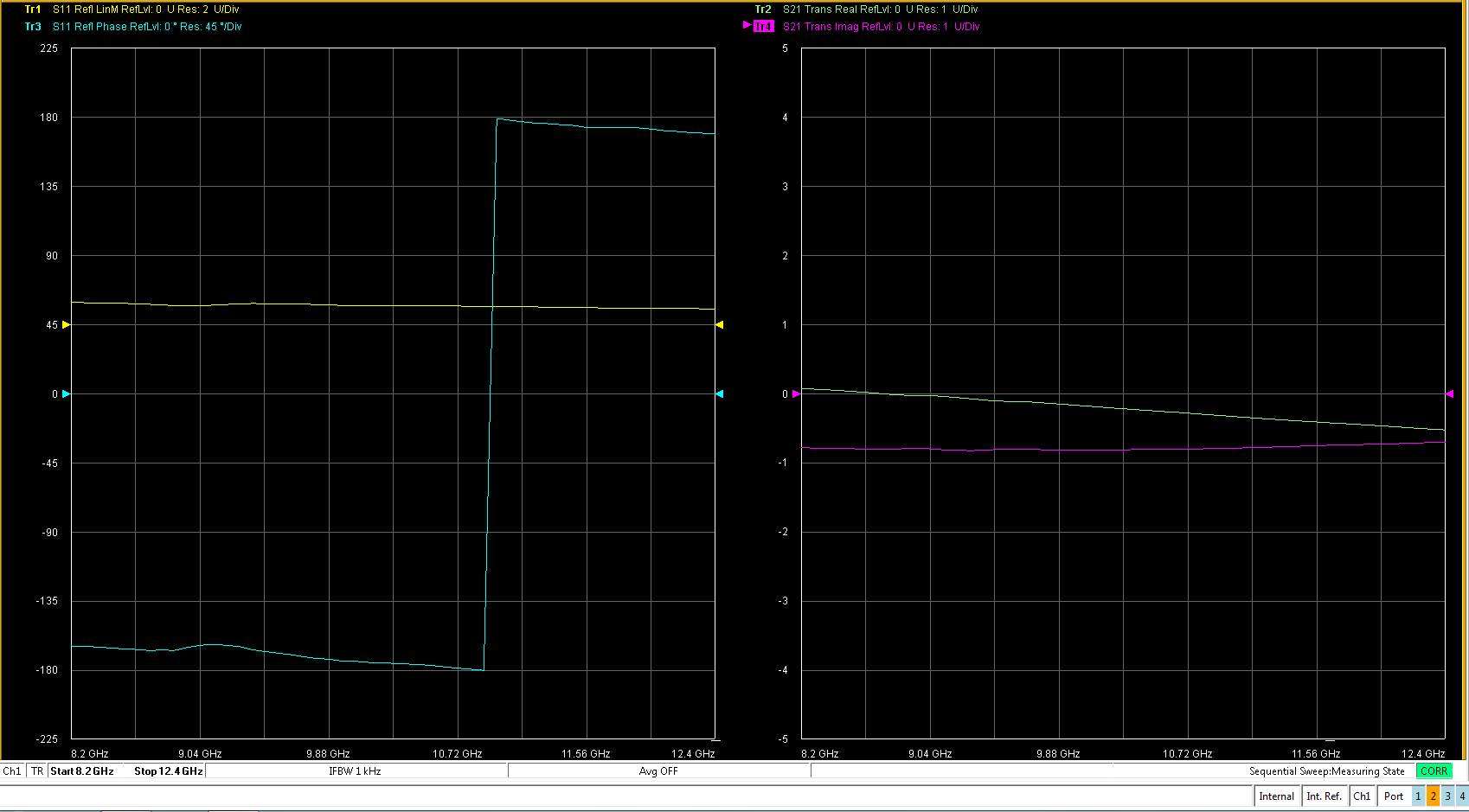
VNA screenshots showing S-parameters in different formats.
In some other applications, such as paint/coating thickness on a conducting substrate, phase information may be of interest. In this case the phase of the reflected signal can be readily correlated to the thickness of the coating. To do this, one would simply need a phase sensitive measurement approach, which can be achieved by combining a portion of the transmitted signal with a portion of the reflected signal and passing the combination through a mixer, which is a 3-port microwave device that combines two input signals for frequency conversion purposes (e.g., up-converting or down-converting). In this way and using some relevant calibration scheme, the mixer output which is a simple DC voltage can be correlated to the coating thickness. This type of a measurement system can be easily manufactured using waveguide components or printed circuit board (PCB) technology rendering the overall system compact, inexpensive and easy-to-use. Schematics of a phase detector and power meter are shown below. It should be noted that these are general schematics and that there are many variations that depend on the application, requirements, and constraints.
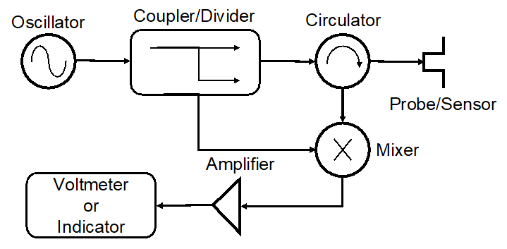
Phase Detector Schematic.
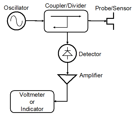
Power meter schematic.
In a similar manner, the power associated with the transmitted signal may be of interest. In this case, a commercial power meter of custom-designed one (i.e., a Schottky diode detector) may be employed using the methodology explained above.