Magnetic Field Indicators
Determining whether a magnetic field is of adequate strength and in the proper direction is critical when performing magnetic particle testing. As discussed previously, knowing the direction of the field is important because the field should be as close to perpendicular to the defect as possible and no more than 45 degrees from normal. Being able to evaluate the field direction and strength is especially important when inspecting with a multidirectional machine, because when the fields are not balanced properly, a vector field will be produced that may not detect some defects.
There is actually no easy-to-apply method that permits an exact measurement of field intensity at a given point within a material. In order to measure the field strength, it is necessary to intercept the flux lines. This is impossible without cutting into the material and cutting the material would immediately change the field within the part. However, cutting a small slot or hole into the material and measuring the leakage field that crosses the air gap with a Gauss meter is probably the best way to get an estimate of the actual field strength within a part. Nevertheless, there are a number of tools and methods available that are used to determine the presence and direction of the field surrounding a component.
Ketos Ring
Prior to the inspection, a system performance verifier is often used to ensure that the system is delivering the proper amount of current as called for during the inspection. Within the NDE industry there are a number of different standard process control specimens used to aid in verifying the performance of the electromagnetic system. Some of the devices used include: the ISO ring (also known as Reference Block Type 1 (MTU-3)), ISO block (also known as MTU-2), and the AS 5282 ring (or similar Ketos ring), shown in Figure 3. These items are a means to verify the operation of the system, and should be used on a periodic basis during the operation of the system. Suggested times may be at the beginning of each shift change, or at the beginning of the inspection process if the bench is not used on a daily basis. For a system such as yoke, a prescribed test such as a dead weight test may be performed to ensure a proper amount of magnetic field is generated.
The AS 5282 ring, and similarly the Ketos ring, is a ring that is made up of a series of pre-drilled holes at increasing depths below the surface used to simulate sub-surface defects. The distance of the holes to the surface increases as you move to holes of increasing number. Its original purpose was to demonstrate the ability to use MPI to find sub-surface flaws, but it has long since been used to perform regular performance evaluation of MPI bench systems. The intensity of the indication depends on the depth of the flaw and the amount of current passed through a central bar conductor as shown in Figure 4.

When the magnetic particle fluid is applied, it contacts the surface with enough fluid flow to wash away any indications being formed by the magnetic leakage fields caused by the drilled holes. For this reason, the indications are developed by a final magnetizing shot or shots, which are triggered immediately after the direct fluid flow is diverted. Orientation of the ring with respect to the fluid flow can have a significant impact on which lines develop indications with lines near the area where the fluid is applied often proving more difficult for indications to develop.
Gauss Meter or Hall Effect Gage
A Gauss meter with a Hall Effect probe is commonly used to measure the tangential field strength on the surface of the part. As discussed in some detail on the "Measuring Magnetic Fields" page, the Hall effect is the transverse electric field created in a conductor when placed in a magnetic field. Gauss meters, also called Tesla meters, are used to measure the strength of a field tangential to the surface of the magnetized test object. The meters measure the intensity of the field in the air adjacent to the component when a magnetic field is applied.
The advantages of Hall effect devices are: they provide a quantitative measure of the strength of magnetizing force tangential to the surface of a test piece, they can be used for measurement of residual magnetic fields, and they can be used repetitively. Their main disadvantages are that they must be periodically calibrated and they cannot be used to establish the balance of fields in multidirectional applications.
Quantitative Quality Indicator (QQI)
The Quantitative Quality Indicator (QQI) or Artificial Flaw Standard is often the preferred method of assuring proper field direction and adequate field strength. The use of a QQI is also the only practical way of ensuring balanced field intensity and direction in multiple-direction magnetization equipment. QQIs are often used in conjunction with a Gauss meter to establish the inspection procedure for a particular component. They are used with the wet method only, and like other flux sharing devices, can only be used with continuous magnetization.
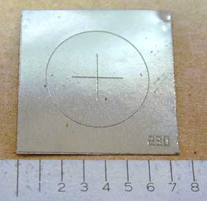
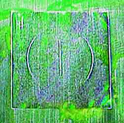
The QQI is a thin strip of either 0.002 or 0.004 inch thick AISI 1005 steel. A photoetch process is used to inscribe a specific pattern, such as concentric circles or a plus sign. QQIs are nominally 3/4 inch square, but miniature shims are also available. QQIs must be in intimate contact with the part being evaluated. This is accomplished by placing the shim on a part etched side down, and taping or gluing it to the surface. The component is then magnetized and particles applied. When the field strength is adequate, the particles will adhere over the engraved pattern and provide information about the field direction. When a multidirectional technique is used, a balance of the fields is noted when all areas of the QQI produce indications.
Some of the advantages of QQIs are: they can be quantified and related to other parameters, they can accommodate virtually any configuration with suitable selection, and they can be reused with careful application and removal practices. Some of the disadvantages are: the application process is somewhat slow, the parts must be clean and dry, shims cannot be used as a residual magnetism indicator as they are a flux sharing device, they can be easily damaged with improper handling, and they will corrode if not cleaned and properly stored.


Above left is a photo of a typical QQI shim. The photo on the right shows the indication produced by the QQI when it is applied to the surface a part and a magnetic field is established that runs across the shim from right to left.
Pie Gage
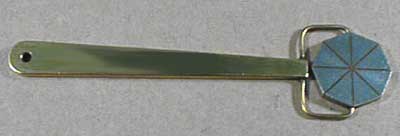
The pie gage is a disk of highly permeable material divided into four, six, or eight sections by nonferromagnetic material. The divisions serve as artificial defects that radiate out in different directions from the center. The diameter of the gage is 3/4 to 1 inch. The divisions between the low carbon steel pie sections are to be no greater than 1/32 inch. The sections are furnace brazed and copper plated. The gage is placed on the test piece copper side up and the test piece is magnetized. After particles are applied and the excess removed, the indications provide the inspector the orientation of the magnetic field.

The principal application is on flat surfaces such as weldments or steel castings where dry powder is used with a yoke or prods. The pie gage is not recommended for precision parts with complex shapes, for wet-method applications, or for proving field magnitude. The gage should be demagnetized between readings.
Several of the main advantages of the pie gage are that it is easy to use and it can be used indefinitely without deterioration. The pie gage has several disadvantages, which include: it retains some residual magnetism so indications will prevail after removal of the source of magnetization, it can only be used in relatively flat areas, and it cannot be reliably used for determination of balanced fields in multidirectional magnetization.
Watch this short movie to see a Pie field gage in action (600KB mov).
Slotted Strips
Slotted strips, also known as Burmah-Castrol Strips, are pieces of highly permeable ferromagnetic material with slots of different widths. They are placed on the test object as it is inspected. The indications produced on the strips give the inspector a general idea of the field strength in a particular area.
Advantages of these strips are: they are relatively easily applied to the component, they can be used successfully with either the wet or dry method when using the continuous magnetization, they are repeatable as long as orientation to the magnetic field is maintained, and they can be used repetitively. Some of the disadvantages are that they cannot be bent to complex configuration and they are not suitable for multidirectional field applications since they indicate defects in only one direction.