Impedance Phase Shift
|
Where: ϕ = Phase Angle (deg) X = Reactance(ohm) R = Resistance (ohm) |
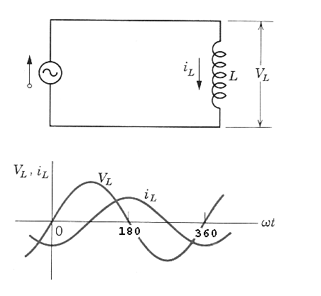
Although both the current and the voltage oscillate sinusoidally in an AC circuit they do not necessarily rise and fall simultaneously with each other. The current and voltage will oscillate with the same frequency but they will only be in-phase if the circuit contains only resistance (or if the circuit is in resonance). In this case, when the voltage is at it's maximum, the current will also be at its maximum, and the impedance purely real. However, when a circuit also contains reactance, the voltage and the current shift out of phase. This shift occurs because when the change in current is highest, it will create the greatest amount of inductive reactance (XL)in the circuit. While the capacitive reactance Xc also contributes, it is insignificant during eddy current tests compared to XL. This inductive reactance is responsible for the voltage across the inductor. See these pages for a better explanation of inductive reactance and phase shift.
The angle by which the sine curve of the voltage in a circuit leads or lags the sine curve of the current in the circuit is called the phase angle (f). If f is positive the voltage leads the current. The phase angle can be determined from the components of impedance that make up the circuit. The phase angle can be calculated from the simple trigonometric relationship between the inductive reactance and the resistance on the impedance plane. It can also be seen from the impedance plane that when the total impedance and the phase angle are known, the individual components of the impedance (inductive reactance and resistance) can be calculated. This is what occurs most often in practice. Most instruments measure the total impedance and the phase angle between the drive current and the voltage across the coil. This information can then be used to calculate the resistance and inductive reactance components of the signal if needed.
