Surface Breaking Cracks
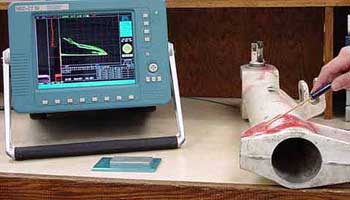
 Eddy current equipment can be used for a variety of applications such as the detection of cracks (discontinuities), measurement of metal thickness, detection of metal thinning due to corrosion and erosion, determination of coating thickness, and the measurement of electrical conductivity and magnetic permeability. Eddy current inspection is an excellent method for detecting surface and near surface defects when the probable defect location and orientation is well known.
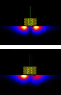
Defects such as cracks are detected when they disrupt the path of eddy currents and weaken their strength. The images to the right show an eddy current surface probe on the surface of a conductive component. The strength of the eddy currents under the coil of the probe ins indicated by color. In the lower image, there is a flaw under the right side of the coil and it can be see that the eddy currents are weaker in this area.
Of course, factors such as the type of material, surface finish and condition of the material, the design of the probe, and many other factors can affect the sensitivity of the inspection. Successful detection of surface breaking and near surface cracks requires:
- A knowledge of probable defect type, position, and orientation.
- Selection of the proper probe. The probe should fit the geometry of the part and the coil must produce eddy currents that will be disrupted by the flaw.
- Selection of a reasonable probe drive frequency. For surface flaws, the frequency should be as high as possible for maximum resolution and high sensitivity. For subsurface flaws, lower frequencies are necessary to get the required depth of penetration and this results in less sensitivity. Ferromagnetic or highly conductive materials require the use of an even lower frequency to arrive at some level of penetration.
- Setup or reference specimens of similar material to the component being inspected and with features that are representative of the defect or condition being inspected for.
 The basic steps in performing an inspection with a surface probe are the following:
- Select and setup the instrument and probe.
- Select a frequency to produce the desired depth of penetration.
- Adjust the instrument to obtain an easily recognizable defect response using a calibration standard or setup specimen.
- Place the inspection probe (coil) on the component surface and null the instrument.
- Scan the probe over part of the surface in a pattern that will provide complete coverage of the area being inspected. Care must be taken to maintain the same probe-to-surface orientation as probe wobble can affect interpretation of the signal. In some cases, fixtures to help maintain orientation or automated scanners may be required.
- Monitor the signal for a local change in impedance that will occur as the probe moves over a discontinuity.
The applet below depicts a simple eddy current probe near the surface of a calibration specimen. Move the probe over the surface of the specimen and compare the signal responses from a surface breaking crack with the signals from the calibration notches. The inspection can be made at a couple of different frequencies to get a feel for the effect that frequency has on sensitivity in this application.