Acoustic Emission Source Location Techniques
Multi-Channel Source Location Techniques
Locating the source of significant acoustic emissions is often the main goal of an inspection. Although the magnitude of the damage may be unknown after AE analysis, follow up testing at source locations can provide these answers. As previously mentioned, many AE systems are capable of using multiple sensors/channels during testing, allowing them to record a hit from a single AE event. These AE systems can be used to determine the location of an event source. As hits are recorded by each sensor/channel, the source can be located by knowing the velocity of the wave in the material and the difference in hit arrival times among the sensors, as measured by hardware circuitry or computer software. By properly spacing the sensors in this manner, it is possible to inspect an entire structure with relatively few sensors.
Source location techniques assume that AE waves travel at a constant velocity in a material. However, various effects may alter the expected velocity of the AE waves (e.g. reflections and multiple wave modes) and can affect the accuracy of this technique. Therefore, the geometric effects of the structure being tested and the operating frequency of the AE system must be considered when determining whether a particular source location technique is feasible for a given test structure.

Linear Location Technique
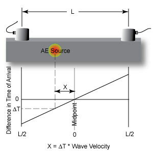
Several source location techniques have been developed based on this method. One of the commonly used computed-source location techniques is the linear location principle shown to the right. Linear location is often used to evaluate struts on truss bridges. When the source is located at the midpoint, the time of arrival difference for the wave at the two sensors is zero. If the source is closer to one of the sensors, a difference in arrival times is measured. To calculate the distance of the source location from the midpoint, the arrival time is multiplied by the wave velocity. Whether the location lies to the right or left of the midpoint is determined by which sensor first records the hit. This is a linear relationship and applies to any event sources between the sensors.
Because the above scenario implicitly assumes that the source is on a line passing through the two sensors, it is only valid for a linear problem. When using AE to identify a source location in a planar material, three or more sensors are used, and the optimal position of the source is between the sensors. Two categories of source location analysis are used for this situation: zonal location and point location.
Zonal Location Technique

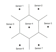
 As the name implies, zonal location aims to trace the waves to a specific zone or region around a sensor. This method is used in anisotropic materials or in other structures where sensors are spaced relatively far apart or when high material attenuation affects the quality of signals at multiple sensors. Zones can be lengths, areas or volumes depending on the dimensions of the array. A planar sensor array with detection by one sensor is shown in the upper right figure. The source can be assumed to be within the region and less than halfway between sensors.
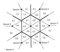
When additional sensors are applied, arrival times and amplitudes help pinpoint the source zone. The ordered pair in lower right figure represents the two sensors detecting the signal in the zone and the order of signal arrival at each sensor. When relating signal strength to peak amplitude, the largest peak amplitude is assumed to come from the nearest sensor, second largest from the next closest sensor and so forth.
Point Location
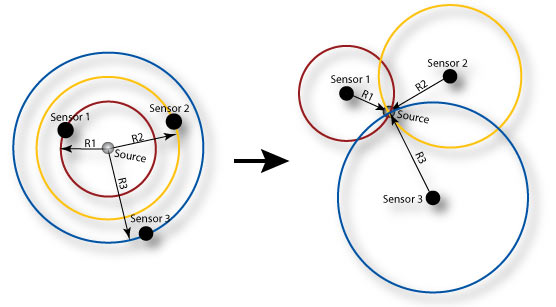
In order for point location to be justified, signals must be detected in a minimum number of sensors: two for linear, three for planar, four for volumetric. Accurate arrival times must also be available. Arrival times are often found by using peak amplitude or the first threshold crossing. The velocity of wave propagation and exact position of the sensors are necessary criteria as well. Equations can then be derived using sensor array geometry or more complex algebra to locate more specific points of interest.